(Note: This is one of several methods of installing the Topargee water gauge in the Revel. See here and here and here for others.)
Some of us have been pretty dissatisfied with the inaccuracy of the Revel's water gauge, so we decided to supplement it with a more accurate USAGE meter (flowmeter). We identified this model (Topargee H2F-FM Flush Mount Water Gauge) as a good solution, so a couple of us got our Revels together one day and added the flowmeter to our rigs.
The flowmeter is imported from Australia and uses BSP threads, as opposed to the NPT threads that are standard in North America (see more here). Since the flowmeter does not include the fittings that are required to tie it into the Revel's lines, we found and purchased these inexpensive BSP fittings that would work for our application. (1/2" Plastic PEX Barb x BSP Female Swivel Adapter with Clamp).

Here are the steps that we took.
We drilled out the rivets so that the panel could be removed. When reassembling, we used simple bolts & nuts to replace the rivets.

The flowmeter can be installed on the water line before or after the water pump, but it must be 8" from any 90-degree bends in the water line. As it turns out, the Revel does not have enough room after the pump to meet this criterion, so we installed it BEFORE the pump, meaning that the line is not under pressure, but it IS under vacuum. In the picture below, the red circle indicates the bottom of the line that we installed the flowmeter in.


This exposed the following view:

Unscrewing the top and bottom of the white water line allowed us to slip the line out of the Revel. You can see that there was a bad kink in the line ever since it was installed at the Winnebago factory.

The flowmeter must be installed 8" from any 90-degree bend, so we measured 8" from each end, marked the section, and removed the piece in the middle. The flowmeter will be spliced into the line here.

Presumably due to the slight differences between BSP and NPT fittings, we had to slightly grind the fixtures down a few thousands of an inch to ensure a proper fit. We used a drill chuck and a file to grind the outsides of the fixtures down to the proper size, and we used a drill bit to slightly ream the water gauge opening.


We assembled the pieces, applied a bead of silicone to ensure that the vacuum would be maintained, and tightened the connections with fuel injection clamps.
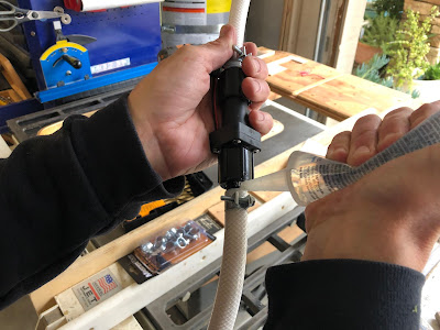
Here is the final assembly, flowmeter is the black cylinder in the center.

We installed the line back in the Revel by sliding it into place from above, then applied teflon tape to the fixture threads (remember that teflon tape must be applied in the direction of the threads) and tightened the fixtures.
The next step was to cut a hole in the galley to accommodate the flowmeter's new water gauge display. Jim created a template so that we could draw the perfect rectangle to guide the saw. We also stuffed the drawer opening below it with some sheets of paper to catch the wood shavings.

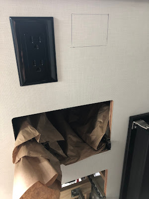
We used an oscillating saw to cut the opening.

We added a few small notches to accommodate the wires from the display.

The display was installed under the sink and to the left. Note that the display is meant to viewed directly, so we have to squat down to read the display (it only has 8 vertical degrees of legibility, which is less than ideal).

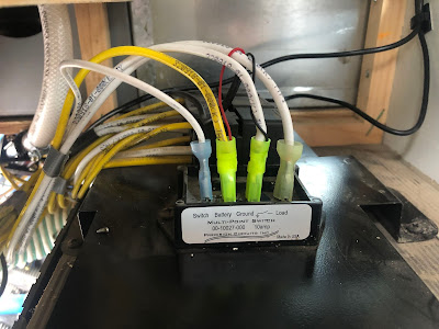
Finally, we tapped into the existing 12-volt power that is in the bottom of the galley, conveniently located near the water pump. Note the small red and black wires from the flowmeter that were added to the 12-volt disconnects (we installed new disconnects).
After running some tests, we've determined that the 21 gallon tank (79.5 liters) has about 20 gallons (75 liters) that can be accessed through the pump, so we calibrated our flowmeters for 75 liters, and now have about 19x more resolution into our water tank than we had before.

If all goes smoothly, I'd estimate 3-4 hours to complete the job, and about $160 in materials (including the flowmeter).
Some of us have been pretty dissatisfied with the inaccuracy of the Revel's water gauge, so we decided to supplement it with a more accurate USAGE meter (flowmeter). We identified this model (Topargee H2F-FM Flush Mount Water Gauge) as a good solution, so a couple of us got our Revels together one day and added the flowmeter to our rigs.
The flowmeter is imported from Australia and uses BSP threads, as opposed to the NPT threads that are standard in North America (see more here). Since the flowmeter does not include the fittings that are required to tie it into the Revel's lines, we found and purchased these inexpensive BSP fittings that would work for our application. (1/2" Plastic PEX Barb x BSP Female Swivel Adapter with Clamp).

Here are the steps that we took.
We drilled out the rivets so that the panel could be removed. When reassembling, we used simple bolts & nuts to replace the rivets.

The flowmeter can be installed on the water line before or after the water pump, but it must be 8" from any 90-degree bends in the water line. As it turns out, the Revel does not have enough room after the pump to meet this criterion, so we installed it BEFORE the pump, meaning that the line is not under pressure, but it IS under vacuum. In the picture below, the red circle indicates the bottom of the line that we installed the flowmeter in.

We removed the galley's side vent and the drawers to get better access.


Unscrewing the top and bottom of the white water line allowed us to slip the line out of the Revel. You can see that there was a bad kink in the line ever since it was installed at the Winnebago factory.

The flowmeter must be installed 8" from any 90-degree bend, so we measured 8" from each end, marked the section, and removed the piece in the middle. The flowmeter will be spliced into the line here.

Presumably due to the slight differences between BSP and NPT fittings, we had to slightly grind the fixtures down a few thousands of an inch to ensure a proper fit. We used a drill chuck and a file to grind the outsides of the fixtures down to the proper size, and we used a drill bit to slightly ream the water gauge opening.


We assembled the pieces, applied a bead of silicone to ensure that the vacuum would be maintained, and tightened the connections with fuel injection clamps.

Here is the final assembly, flowmeter is the black cylinder in the center.

The next step was to cut a hole in the galley to accommodate the flowmeter's new water gauge display. Jim created a template so that we could draw the perfect rectangle to guide the saw. We also stuffed the drawer opening below it with some sheets of paper to catch the wood shavings.


We used an oscillating saw to cut the opening.

We added a few small notches to accommodate the wires from the display.

The display was installed under the sink and to the left. Note that the display is meant to viewed directly, so we have to squat down to read the display (it only has 8 vertical degrees of legibility, which is less than ideal).

Finally, we tapped into the existing 12-volt power that is in the bottom of the galley, conveniently located near the water pump. Note the small red and black wires from the flowmeter that were added to the 12-volt disconnects (we installed new disconnects).

After running some tests, we've determined that the 21 gallon tank (79.5 liters) has about 20 gallons (75 liters) that can be accessed through the pump, so we calibrated our flowmeters for 75 liters, and now have about 19x more resolution into our water tank than we had before.

If all goes smoothly, I'd estimate 3-4 hours to complete the job, and about $160 in materials (including the flowmeter).
1 comment:
Hi Jeff. Thank you for all the great info on your mods! I have questions related to this mod, but I don't want to replace the water gauge. I just want to fix a leak in the footwell. I can see that there's a leak coming from the 90 deg connection on the sprayer. I think a lot of folks just cap this section off b/c it's a common fail point.
I've never worked with PEX before (no van plumbing experience at all, but I think I understand the basics). I'm guessing I need to cut the PEX pipe behind that connection and then cap it off. I'll need a PEX pipe cutter and the plug (with clamp ring). Do you have a suggestion for which PEX pipe cutter I might use? I haven't totally removed the cover yet (I just removed all the necessary screws and pulled it out enough to see where the leak is coming from). Seems like there's several pieces that need to be removed to get the cover off.
Thanks in advance for any help!
Kim
Post a Comment