Water Gauge Replacement (Loeza Method)

(Note: This is one of several methods of installing the Topargee water gauge in the Revel. See here and here and here for others.)

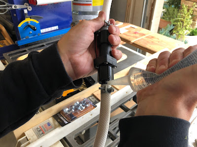
This what I did, no drilling needed. Just made the pipe, then slid it underneath the existing plumbing without removing the panel, then just made the two connections.  Tightened connection at winterizing valve first, then at pump.  This is the same hose you guys put the flow meter on, the hose from the winterizing valve to the inlet of the water pump (suction side).  It took 30 to 45 minutes to do.  I tied into power and ground at the switch for the running board light.

The special order fitting from Home Depot is this one.
(https://www.homedepot.com/p/Ecopoly-1-2-in-Plastic-PEX-Barb-x-1-2-in-BSP-Female-Swivel-Adapter-5-Pack-32873/308745733)


Water Gauge Replacement (Hill Method)

(Note: This is one of several methods of installing the Topargee water gauge in the Revel. See here and here and here for others.)

Topargee Water Gauge Install and Plumbing Cleanup


The remaining water in the fresh tank as reported by the One Place is useless to me.  When there is 71% of capacity remaining, it reports 1/3 remaining. When there is 10% remaining, it reports empty.  During the range of 71% to 10% you have no idea where you are in that range. That is not very useful because that is the time when I really want to know how much water I have.

With input from Jeff and Jim I decided to install a Topargee “water tank gauge” with a flush mount display https://aquaviewinc.com/product/h2f-fm/. The Topargee is not really a water tank gauge. It measures the flow of water leaving the tank. It is surprisingly accurate and much more useful than the One Place.  I chose the option with the flush mount display rather than the BlueTooth version because I thought the display would likely last longer than the company will be able to keep the iOS app updated. (Thanks to Jeff for this pro tip). There are two cons to this gauge that I know of: you have to remember to reset it when filling the water tank, and there is no easy way to tell it that you just added 5 gallons of water.

I installed the display in the front of the galley cabinet (again, as suggested by Jeff and illustrated to me in pictures by Jim). This is not the best as the display is much easier to read from below than above. I did not see any easy way to run the wires somewhere else with a better viewing angle, so this is where it is.

The instructions say to mount the flow sensor in the middle of a straight run of pipe 400mm (about 16”) long. To get a straight run of pipe and to clean up the mess of fittings in the footwell area, I decided to reorganize all the plumbing. Fortunately, this mostly meant removing things. I eliminated everything I do not need:

  • the water dump valve and its connections to the output from the pump,
  • the antifreeze intake hose port and valve, 
  • the spray port and 
  • the hose fill port. 

What remains in the foot well are:

  • gravity fill,
  • from tank to pump,
  • from pump to the rest of water system,
  • from water heater to sink.


I added an air hose connection and selector valve for blowing out the system with air for winterization.

This simplifies things a lot (I have a big pile of little pieces of PEX and PEX fittings that I removed) and greatly reduces the risk of freeze damage. The air hose connection is made almost entirely of parts that were removed. The only part I had to buy was a 1/2” male to 1/4” female adapter. I used an air hose connector with 1/4” male thread that I had in my box of air hose parts.

The key to getting the run of straight pipe for the flow sensor is to modify how water gets from the pump to the sink and the rest of the system. Originally, the flex pipe from the pump went to a tee that sent water up to the sink or down to everything else. I changed this by replacing the tee with an elbow so the water went up. I then put the flow sensor in the middle of the vertical pipe and added a tee near the sink to send the water back down to everything else. This was a pretty simple plumbing change.

I wanted to preserve the flexible white hoses on either side of the pump as these are supposed to help reduce noise from the pump. Ideally, they should not touch anything as they get shaken a lot when the pump is pumping.

The only challenges I had with this job were:


  • Finding fittings to adapt the BSP fittings on the Topargee sensor to PEX. In the end I gave up trying to find a suitable BSP connector (after buying two different ones, one of which I tried to modify) and went simple with a 1/2” female NPT to PEX connector from Home Depot: https://www.homedepot.com/p/Apollo-1-2-in-Brass-PEX-Barb-x-1-2-in-Female-Pipe-Thread-Adapter-APXFA1212/301541029  NPT threads are not supposed to seal to BSP threads, but with 4 turns of teflon tape and a little pipe dope, and then thoroughly tightening, it seals just fine. The pipe dope probably is not needed. I think this is the way to go for most people. But Gus at Aqua View says that if you can get a nylon fitting, which he says are easy to get at RV parts places, it might work better than brass. The important thing is to not get a swivel fitting, which is what I tried at first. Swivel fittings seal with a washer so they should seal to BSP, but they have a central part holding the washer. This part would normally fit inside the pipe screwed into the fitting. The Topargee water flow sensor has a narrower internal diameter than pipe and this part will not fit inside the sensor. This is why Jeff and Jim had to modify their swivel fittings and sensors.
  • Taking apart the existing PEX can be a challenge. If you do not need to connect to existing pipe, you can simply cut it and toss it. But sometimes you need to keep something that is there or want to reuse something. With a little practice it is easy to take the crimp rings off with a pair of diagonal cutters. I got pretty fast at this. The trick is to lift up the end of the ring that is exposed, by squeezing between it and the little tab the sticks up with your diagonal cutters. Then you can grab the end and peel it up. Once the ring is loose the PEX is not easy to pull off because it is distorted by the ring and retains this distorted shape. Gentle heating with a heat gun causes the PEX to return to its original shape allowing it to be pulled apart easily. Just heat until the indentations left by the ring start to smooth out a bit. I reused both the PEX and some fittings. I do not know if reuse is recommended, but where you connect to the existing plumbing there may be no choice. When I have a choice, I use new parts.


I had no experience with PEX and no PEX tools so I used PEXLock connectors. No special tools are needed-just big pliers. I found them easy to use and they can be removed and reused (I needed this!). If you only plan to do a little work with PEX this may be a better approach than getting a special crimping tool. https://flairit.com/product-category/pexlock-fittings/ 

Finally, because I no longer need the “city fill” on the drivers side (I only used it for blowing out the system with air) I drained it and capped the connections. This required a 1/2” NPT cap and 1/2” NPT plug from my local hardware store. This was easy. Now there is no risk of the water in this line freezing where it penetrates the exterior of the van.

I wired the Topargee in parallel with the water pump so that it gets power when the pump gets power.


The water display for the Topargee between the electrical outlet and the switches for the pump and macerator.


The footwell area under the galley cabinet after I was finished. Not much here. The valve used to select input from anti-freeze instead of the tank was reused to select between the tank and the air hose fitting as the source for the water system. The valve and air hose fitting are inside and covered normally. I want them to be safe from freezing in severe weather.


Close up of what is left in the footwell with an air hose connected and the valve set to air as the source. I am blowing out the system.


Inside the galley cabinet.


Looking into the footwell from where the refrigerator goes. Compared to before, there is hardly anything here.


I made a temporary cover out of some closed-cell foam. This should work until I come up with a plan for a permanent cover.


White cap (seals with teflon tape applied to threads on the tee) and plug (seals with existing washer) on a threaded tee and elbow to disconnect the city fill port and eliminate the risk of the port freezing. This is beside the thermostatic mixing valve under the bench.

Water Gauge Replacement (Lincoln Method)

(Note: This is one of several methods of installing the Topargee water gauge in the Revel. See here and here and here for others.)

Some of us have been pretty dissatisfied with the inaccuracy of the Revel's water gauge, so we decided to supplement it with a more accurate USAGE meter (flowmeter). We identified this model (Topargee H2F-FM Flush Mount Water Gauge) as a good solution, so a couple of us got our Revels together one day and added the flowmeter to our rigs.

The flowmeter is imported from Australia and uses BSP threads, as opposed to the NPT threads that are standard in North America (see more here). Since the flowmeter does not include the fittings that are required to tie it into the Revel's lines, we found and purchased these inexpensive BSP fittings that would work for our application. (1/2" Plastic PEX Barb x BSP Female Swivel Adapter with Clamp).


Here are the steps that we took.

We drilled out the rivets so that the panel could be removed. When reassembling, we used simple bolts & nuts to replace the rivets.


The flowmeter can be installed on the water line before or after the water pump, but it must be 8" from any 90-degree bends in the water line. As it turns out, the Revel does not have enough room after the pump to meet this criterion, so we installed it BEFORE the pump, meaning that the line is not under pressure, but it IS under vacuum.  In the picture below, the red circle indicates the bottom  of the line that we installed the flowmeter in.

We removed the galley's side vent and the drawers to get better access. 


This exposed the following view:

Unscrewing the top and bottom of the white water line allowed us to slip the line out of the Revel. You can see that there was a bad kink in the line ever since it was installed at the Winnebago factory.


The flowmeter must be installed 8" from any 90-degree bend, so we measured 8" from each end, marked the section, and removed the piece in the middle. The flowmeter will be spliced into the line here.


Presumably due to the slight differences between BSP and NPT fittings, we had to slightly grind the fixtures down a few thousands of an inch to ensure a proper fit. We used a drill chuck and a file to grind the outsides of the fixtures down to the proper size, and we used a drill bit to slightly ream the water gauge opening.


We assembled the pieces, applied a bead of silicone to ensure that the vacuum would be maintained, and tightened the connections with fuel injection clamps.


Here is the final assembly, flowmeter is the black cylinder in the center.


We installed the line back in the Revel by sliding it into place from above, then applied teflon tape to the fixture threads (remember that teflon tape must be applied in the direction of the threads) and tightened the fixtures.

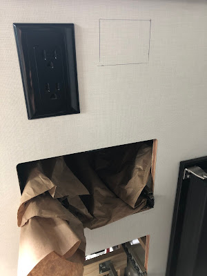
The next step was to cut a hole in the galley to accommodate the flowmeter's new water gauge display. Jim created a template so that we could draw the perfect rectangle to guide the saw. We also stuffed the drawer opening below it with some sheets of paper to catch the wood shavings.


We used an oscillating saw to cut the opening.


We added a few small notches to accommodate the wires from the display.


The display was installed under the sink and to the left. Note that the display is meant to viewed directly, so we have to squat down to read the display (it only has 8 vertical degrees of legibility, which is less than ideal).


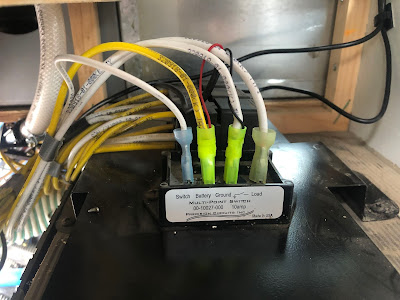
Finally, we tapped into the existing 12-volt power that is in the bottom of the galley, conveniently located near the water pump. Note the small red and black wires from the flowmeter that were added to the 12-volt disconnects (we installed new disconnects).


After running some tests, we've determined that the 21 gallon tank (79.5 liters) has about 20 gallons (75 liters) that can be accessed through the pump, so we calibrated our flowmeters for 75 liters, and now have about 19x more resolution into our water tank than we had before.

If all goes smoothly, I'd estimate 3-4 hours to complete the job, and about $160 in materials (including the flowmeter).


Bottle Hook

I sometimes need to get a drink in the middle of the night, but I sleep near the back door, and there's no good place to store my water bottle. I decided to repurpose one of the snap screws as a way to anchor a hook for my water bottle. 

I used a 'rope hook' and a #8 1 1/2" self-drilling screw, costing about $2.00.


Update 2020:
This was a big success, so my wife wanted one on her side. I used a slightly smaller hook (https://smile.amazon.com/gp/product/B000BQMUJ2/) and reused one of the holes from the 'bed seat belt' that I had removed.  Works great.


Dec-19-2019